Tuesday, March 27, 2012

Strain gauges

In the Velociryder versions 1-3, turning was achieved using a tilting rear section. This tilting section prevented the back foot from helping the rider balance forward and backwards. I would not stand for this in version 4. I planned to use an actual skateboard deck and strain gauges to measure the tilt of the rider. This will minimize moving parts and ideally make it easier to ride. Not only that, knowing the weight of the rider can improve the board's response.

Part 1: Acquiring Strain Gauges

After some Googling and ebaying, I found strain gauges or pressure sensors either come in tiny or extra large, 1-3 pound range or industrial strength. All were too expensive. Then I realized digital bathroom scales must have something to measure weight. And since they're designed to both precisely measure human weights and not break under the heaviest of people, they are perfect. A quick search revealed digital bathroom scales going on eBay for a dollar.

Kilograms only? Good enough!
Disassembly followed. The strain gauges look like this.
It is supported by the side prongs. Pressure is applied on the top of the middle prong.

Part 2: Analysis

Electrically, they look like a potentiometer.


The outer blue and white wires measure a constant resistance, in this case 2 kOhms, while the middle red wire is the wiper, with roughly 1 kOhm resistance between the red and blue wire and the red and white wire. Pressing the gauge is equivalent to turning the potentiometer, though only a very slight amount. When five volts was applied to the outer wires, the middle wire deviated by about 4 millivolts over the range of 100-ish pounds. Since I had four, I used two pairs, one pair each for the left and right side. The power supply for each pair was put in opposition, so pressing on a pair of strain gauges causes one output voltage to go up, and the other to go down.

Left strain gauge/potentiometer goes up under pressure, right side goes down.
This create the biggest difference to amplify for your buck.

Electrically, it forms a wheatstone bridge. Measuring the voltage across the outputs gives a reading that varies linearly with pressure applied.
A wheatstone bridge. Voltage is measured in the middle.
The two strain gauges fully connected. Remember, one is connected upside down to get a differential voltage.


Part 3: Using Them

The tiny voltage difference needs to be beefed up. In comes a differential amplifier!
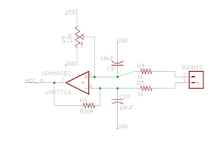
One channel of the differential amplifier with zero point adjustment and low pass filters. The Velociryder uses two, for the right and left side.
This is an almost standard diff amp configuration, with a couple extra bits. The capacitors C8 and C10 are (very) low pass filters to get rid of noise. Instead of a constant resistor on the non-inverting input, a potentiometer is used so any zero offset can be tuned out. This converts the range from 0-4 mV to 0-3 V, an excellent range for a microcontroller's ADC.

Protips

Since the op-amp will likely be used in single supply (unipolar) mode, use a rail to rail op-amp so the output won't crap out near 0 and 3 volts.

Thursday, March 1, 2012

Velociryder V4!

I have all these parts and nothing to velociryde on.

First, we had Velociryder V1.

It actually worked.
Then, we had Velociryder V2 for the Inventure Prize.
Woo waterjet aluminum.
This one worked too!
We kinda had Velociryder V3, ambitious but never completed.
I couldn't find a picture, so here's a render. It didn't work.
Now, we will have Velociryder V4!
With 20% more height!

Giving a good view of the encoders and motors.
From the side, showing the small sprocket for the encoder.

New and improved, with:
  • Digital accelerometer and gyroscope, less analog signals to corrupt!
  • No pivoting rear section whatsoever; strain gauges for steering!
  • Actual skateboard deck to stand on!
  • Overengineered 80/20 frame for no structural failures!
  • PIC24H core for double the speed of an Arduino!
  • Quadrature encoders for real motor control!
  • 5 Ah longpack! (That's one more amp-hour than before)!
A bonus effect of using strain gauges to measure steering is that they can also measure the user's weight. With this and wheel encoder information, I can use actual inverted pendulum state space control, instead of PID.

In the time that I have been not posting updates, I have created a control board, complete with DC regulator, super differential amplifiers for the strain gauges, and sensors.

Ooh, aah. And a logo! The actual size is 3.75" x 1.00"
I have almost all the parts and two weeks to finish to go from computer drawings to Velociryding for a certain event and a certain trip. Including programming. Boy am I hoping my circuit design is correct.

There are still a couple kinks I hope will work itself out. The first is the incredibly wide motors are probably going to hit the ground.
Derp.
The second is that the strain gauge turning is completely untested. I hope I can get a good enough difference between the weight on the right and left sides to use.

Welp, here goes another build marathon. I thought I was done with them after the Inventure Prize last semester.

Appendix