Showing posts with label gyro king. Show all posts

Tuesday, July 16, 2013

Gyro King Performance

Gyro King was a finicky robot. Xo and I never got it spinning at our hoped for 6000 RPM, only reaching a measly 2000 RPM. In addition, motors have really low bandwidth compared to their drive circuitry, thanks to inertia and inductance. Thus, while the robot can drift and move while spinning, it was incredibly slow, and by the time you moved anywhere significant, the internal heading would have changed, and your target is somewhere else. Thus, it performed like other melty robots - waiting for the other robot to run into it and break itself. Not very fun, especially when your robot speed determines how much bite the weapon gets, leading to how much energy gets transferred.

In this 2 vs 2 match Gyro King is basically stuck in the corner the entire match. Granted, it only had one motor working at this time, but I don't think the second motor would have changed much.

A much more interesting match. This is at GMX 2012, with both motors working. This match also shows another problem: the weapon teeth have an annoying habit of flying off by shearing the four 6-32 screws holding it on. Here it was because The Hammer's weapon was able to dig underneath the teeth and pull them out. Since the frame is aluminum, it didn't offer much resistance. Gyro King won through a stroke of luck. The Hammer used a toggle switch for main power. It was hit so hard the switch toggled and shut down the robot halfway in the match.

The same competition, but against a nimble opponent. As you can see Gyro King cannot really do anything. It wins only through the error of the opposing operator accidentally driving into the pit, taking himself out of the match.


A fun match against a very capable robot. In the first couple of hits Gyro King's teeth are knocked out. One hit almost sends Gyro King out of the arena. You can really see how the limited mobility prevents it from taking advantage of Dominant Mode's inversion.

In conclusion, Gyro King was a fun project, an experiment in high impact and high strength components and seeing how many types of electronics we can stuff onto a single board, and a test of mettle, but next time I'm building something a little more aggressive.


Sunday, February 24, 2013

Gyro King Electronic Design and the STM32F40RGT6 Microcontroller

Gyroscope

The control board is centered one of Analog Devices' highest rate gyro, the ADXRS649, rated for 20000 degrees per second but extendible to 50000 degrees per second, or around 8000 RPM. We chose the gyroscope as opposed to Open Melt's accelerometer method to avoid noise issues. While accelerometers will pick up any and all vibrations, gyroscopes are quite a bit more noise resistant. This is offset by the difficulty of finding a gyro with a large enough range and having to place the gyro at the exact center of rotation, since applying acceleration to a gyroscope causes error. Otherwise, all the other challenges are there, such as keeping the sensor in a constant position and orientation as the robot spins around and smashes things.

Analog to Digital Converter (ADC)

The gyroscope outputs a 5V analog signal, with zero rotation at 2.5V. This works out to 50 uV per degree, ideally. Our gyroscope ended up with a range of around 65000 degrees per second due to some curious part choices, making it 38 uV per degree. Thus, we needed accuracy in converting the analog to a digital signal. We used a 24-bit, 14 kSPS ADC from TI, the ADS1259.

Microcontroller

The ADC feeds into the STM32F405RGT6, an ARM Cortex-M4 32 bit microcontroller. The microcontroller was provided from Newark, a pretty good place to get parts. Why this microcontroller?

What stands out is this is an extremely high power chip without being weird. First thing we noticed is how little physical space it needs. It uses a standard 3.3 volt input, avoiding a separate 1.7 volt supply. There's no external RAM or even an oscillator required. All it needed was power. Instead of using the giant 20 pin ARM JTAG nonsense, it uses just 4 wires. On a space limited board such as Gyro King's, every square millimeter counts. And in return we got a 168 MHz processor with a floating point unit, allowing us to avoid the performance vs. fixed point tradeoff, extremely powerful timers, which was used in a previous project to control two three-phase motors with center-aligned PWM, dead time, and ADC triggers, and DMA on many peripherals to save your cycles and automate data capture. Notably, it has a completely free toolchain for compiling programs. Although difficult to set up on OSX, it is possible and certainly usable. Finally, this STM32 is RTOS (Real Time Operating System) friendly. We used the open source ChibiOS. This let us use higher level programming, such as multiple threads, and abstracted a lot of the lower level access. All things considered, a solid microcontroller.

Three Phase Motor Control and Drive

While it is entirely possible to generate the drive motors' three phase commutation signals and sense the rotor position directly from the microcontroller, we were pressed on time and feeling a bit lazy. We turned to Allegro MicroSystems' A4960 Automotive Sensorless BLDC controller. These chips perform sensorless commutation, start up, directly drive the motor MOSFETS, and current limiting all from some configuration from the microcontroller and a PWM signal. Using these significantly reduced development time, though we still have to tune all the parameters of commutation, such as dead time, zero crossing window, phase advance, and commutation blank time.

The Allegro controllers directly connect to a trio of half bridges composed of the IRFH5301TR1PBF N-channel MOSFETS, rated for 35A at 30V.

Board Layout and other Doodads

Connectivity was handled by a little Bluetooth doodad, the Roving Networks RN41-I/RM board. It was directly soldered on to the control board. It connected to a laptop running a pygame based GUI displaying things like spin speed, power, and direction. The controller is a PS3 controller.

The control board also had some good ideas, like a few status LEDs and what looks like a bar of ceramic bus capacitors, since electrolytics would not fit height-wise. A digital Hall-effect sensor was also on there to be used for calibration. Ideally, it would function as an on-board tachometer to a magnet held above it, providing an absolute reference for the rate of rotation, but was never implemented in software.

The board used four layers, to provide full ground planes to try to separate the combination of sensitive analog, digital, power regulation, and motor control on a tiny single board.

A notable bad idea was using test pads as the programming header. Due to space limitations we couldn't fit a full through hole header, so we used surface mount test pads. Of course they ripped out.

Conclusion

This was a pretty solid control board, surviving the impacts of robot battle while tracking well enough to provide a near constant direction at speeds up to 2000 RPM, the max we've seen it spin at. The component choices were all well made. We wouldn't use test pads as headers again though. Xo would go on to make a variation of this board with one brushless driver and two brushed drivers, but otherwise similar hardware.

I should also take pictures next time too.

Friday, September 28, 2012

Introducing Gyro King, the Translational Drift Combat Robot, part 1

Like many engineers, I've always been a fan of combat robotics (I know, most of them are remote controlled rather than a true autonomous robot). Well, something changed after going to Dragon*con in 2011, watching Jamison's robots such as DDT perform in the arena, and quickly hacking together a spinning ass bot deemed Melty Butt.
Weighing in at just over a pound.

Yes it is made of wood.
The brief taste of combat robotics spurred Xo and I to create a real melty brain robot. One with better spin up time, and better control than all the others.

About Melty Brain Robots

Melty brain robots, or translational drift robots work by using the drive motors to spin the entire robot. Using sensors to keep track of the robot's orientation at all times, it can selectively slow down a motor at the same time every rotation to "drift" in a direction. Examples of other melty brain robots are Spinning Tortoise and MeltyB.

The great thing about meltys is that the entire robot's mass goes into the weapon, giving it plenty of inertia. The difficult things about them is:
  1. Without some kind of sensing, they are basically uncontrollable
  2. Everything on the robot needs to be shock mounted
Sensing

The end result of the sensors is figuring out what direction the robot is facing at any given instant. There are two general ideas I can come up with. Beacon based, where the robot tracks a stationary object, and inertial based, where inertial sensors tell it the rate of rotation.

The benefits of a beacon system is that it provides an absolute reference on the heading of the robot. Since the beacon is stationary, more assumptions can be made making orientation tracking much easier. The downside is that a beacon system must be chosen. Visible light/infrared systems work as long as there is clear line of sight to the transmitter, and require filtering to eliminate noise. RF based systems would have less a problem with obstructions, and more with noise. Apparently, a system like that approaches radar complexity.

The other method, inertial sensing, allows the robot to be entirely self contained. Rotational velocity can be measured either directly with a gyroscope or indirectly through centripetal acceleration and an accelerometer. Accelerometers are prescaled by placing them at an angle, since in most cases they would saturate. Gyroscopes with that high rate of rotation are difficult to come by, with only the Analog Devices ADXRS649 being anywhere in the required range.

In the end, we decided in gyroscopes, due to gyroscopes requiring no outside components (less things to break), not being radar level signal processing, and less noise than accelerometers.

About Melty Brain Robots

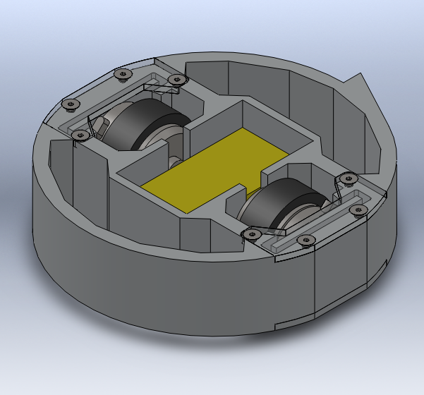
Gyro King was designed to be waterjet out of a 1.5" thick piece of 6061 aluminum plate. Everything needs to be shock mounted. The motors are not rigidly to the frame, but bolted on to plates which are placed in pockets, then wedged in place with Sorbothane to isolate them from shock. Same for the circuit boards, resting in a pocket also lined with Sorbothane, so the traces don't get bounced off.
start

refine

refine more
Finalized
1.3 hour waterjet job
The entire robot can be inscribed in a 6" diameter circle, save for the weapon edge, a O2 tool steel tooth that juts out a quarter inch. The tires are O rings, chosen to be as thin as possible to minimize friction when spinning. Filling the voids in the metal is HDPE cutouts pressed in for weight and rigidity.

Coming soon, details on the control board! Actual tests! Information!

Robot