Friday, September 28, 2012

Introducing Gyro King, the Translational Drift Combat Robot, part 1

Like many engineers, I've always been a fan of combat robotics (I know, most of them are remote controlled rather than a true autonomous robot). Well, something changed after going to Dragon*con in 2011, watching Jamison's robots such as DDT perform in the arena, and quickly hacking together a spinning ass bot deemed Melty Butt.
Weighing in at just over a pound.

Yes it is made of wood.
The brief taste of combat robotics spurred Xo and I to create a real melty brain robot. One with better spin up time, and better control than all the others.

About Melty Brain Robots

Melty brain robots, or translational drift robots work by using the drive motors to spin the entire robot. Using sensors to keep track of the robot's orientation at all times, it can selectively slow down a motor at the same time every rotation to "drift" in a direction. Examples of other melty brain robots are Spinning Tortoise and MeltyB.

The great thing about meltys is that the entire robot's mass goes into the weapon, giving it plenty of inertia. The difficult things about them is:
  1. Without some kind of sensing, they are basically uncontrollable
  2. Everything on the robot needs to be shock mounted
Sensing

The end result of the sensors is figuring out what direction the robot is facing at any given instant. There are two general ideas I can come up with. Beacon based, where the robot tracks a stationary object, and inertial based, where inertial sensors tell it the rate of rotation.

The benefits of a beacon system is that it provides an absolute reference on the heading of the robot. Since the beacon is stationary, more assumptions can be made making orientation tracking much easier. The downside is that a beacon system must be chosen. Visible light/infrared systems work as long as there is clear line of sight to the transmitter, and require filtering to eliminate noise. RF based systems would have less a problem with obstructions, and more with noise. Apparently, a system like that approaches radar complexity.

The other method, inertial sensing, allows the robot to be entirely self contained. Rotational velocity can be measured either directly with a gyroscope or indirectly through centripetal acceleration and an accelerometer. Accelerometers are prescaled by placing them at an angle, since in most cases they would saturate. Gyroscopes with that high rate of rotation are difficult to come by, with only the Analog Devices ADXRS649 being anywhere in the required range.

In the end, we decided in gyroscopes, due to gyroscopes requiring no outside components (less things to break), not being radar level signal processing, and less noise than accelerometers.

About Melty Brain Robots

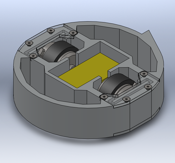
Gyro King was designed to be waterjet out of a 1.5" thick piece of 6061 aluminum plate. Everything needs to be shock mounted. The motors are not rigidly to the frame, but bolted on to plates which are placed in pockets, then wedged in place with Sorbothane to isolate them from shock. Same for the circuit boards, resting in a pocket also lined with Sorbothane, so the traces don't get bounced off.
start

refine

refine more
Finalized
1.3 hour waterjet job
The entire robot can be inscribed in a 6" diameter circle, save for the weapon edge, a O2 tool steel tooth that juts out a quarter inch. The tires are O rings, chosen to be as thin as possible to minimize friction when spinning. Filling the voids in the metal is HDPE cutouts pressed in for weight and rigidity.

Coming soon, details on the control board! Actual tests! Information!

Robot

Tuesday, August 14, 2012

Scooty Upgrades

Edited 08 Sept 2012 to add more pictures of the brake assembly.
Brakes that Work

Due to the failure of the caliper brakes I redesigned the brakes to use band brakes. These brakes work by tightening a band of braking material around a rotating drum. The caveat is that they don't fit on the front wheel, so they have to be placed on the back wheel. While it does eliminate the possibility of going over the handlebars through overzealous braking, it does significantly reduce braking force, something I'm not pleased about. Danger of going over the handlebars can be eliminated through practice. Maximum rear wheel braking force will never change.

Cramming brakes onto the back wheel in addition to the sprocket was a mess. Thankfully, I was able to use the existing bolts going through the rear wheel to also attach the brake drum. The brake band was attached to the side of the motorpod, which was redesigned to include a back footrest. This made my ghetto extended fender obsolete.
It worked enough to survive a couple rides in the rain.
The new motorpod used the existing mounting points as the old one, so it worked pretty well.

Apologies for pictures of the screen, my internet wasn't functional at the time.

Showing the bolts that go through the entire wheel, connecting the hub and sprocket.
The existing 70mm brake hub had a couple holes that almost fit the existing holes. However, after tightening the screws on the wheel, the hub distorted. While it was still usable, it made braking force highly inconsistent. It was either little braking or locked up wheel. Thus, I made a new hub from a scrap hunk of aluminum.

I love the countersink look.
With this new, significantly more concentric brake hub, the brakes work fantastically.
The entire motorpod. The brake band was removed for disassembly so it'll fit in a suitcase.

With the brake band. The wheel is changed because the previous one had a flat was a real pain to remove the inner tube.
Showing the end of the bowden cable.

Nice and compact.
A New Front Wheel

While at Tech, I had a little accident. When the manufacturer warned the wheels I used were not designed for motorized applications, they meant it.
The rim on one side is completely gone.

The impact from falling on the hub smashed it up.

Yeesh.
Luckily I came out of it with only scrapes and sprains.

Learning from my mistakes I changed to a 6 inch steel hub pneumatic wheel (McMaster part number 2717T41). This wheel had already proven itself for the Velociryder. Of course, this meant redesigning the front fork to fit the wider wheel.

While making a new front fork I needed to quickly hack a usable front fork.

teehee

Solidworks and waterjet and annoying milling of steel later is a new front fork.
So much more metal
Chain Stretch

Three days before the end of my internship the chain stretch in my scooter reached a breaking point. After stretching nearly a half link, or 1/4", the chain no longer stays on the sprocket. Time to cut slots to take up the slack and lubricate the chain to keep it from stretching so quickly.

Friday, June 8, 2012

Scooty Brakes (and a stint through the rain)


Using your shoe as a brake is okay for testing, but the wear gets ridiculous. So, I put a few holes in the front fork to mount a plate and the plate to mount a set of brake calipers on the front wheel.

The plate mounts right on the front fork, held on by 6 4-40 screws. The plate is 1/4" steel.
The calipers I used were inexpensive bike calipers from Amazon. While I knew braking onto a plastic rim is not such a good idea, I thought it would still work okay.

Then, parts and assembly, after a particularly nasty ride in the rain back from work.
Ghetto extra waterproofing with masking tape

Still alive!

Yes, that is water on the inside on my caps.

Attaching the brake to the brake plate. Haha what clearance.
Due to the calipers blocking the screws, I had to slowly inch the parts together, screwing down half the screws, moving the caliper around, and screwing down the other half.
Derp.
And then, I got excited and forgot to take more pictures. Long story short, after some testing, I decided they were worse than failure. Not only do the brakes not work, but the brakes and rims must be mortal enemies because they destroy each other. The pads exhibit significant wear and some chunks coming off already, and this is from a nice walking speed.
Overexposed for your dark caliper viewing pleasure.
 On the rim, it seems these bits have melted on. I'm not sure which surface made them.
Can't brush this off. Its melted on.
I can't imagine can guess what would happen slowing from full speed. Rim failure and tire blowout, or I eat through the pads so much they stop applying pressure, or both.

Well, back to the CAD board. This time, I'll use one of these.
70 mm rotor band brake

Sunday, June 3, 2012

Scooty Puff Build

*Note: somehow the styles on this post crapped out and all the headers are tiny. I can't figure it out*

My first build out of real necessity (not something like, I really want a delta robot)! Scooty Puff is a brushless motor powered wonderfully fast Razor style folding scooter.

The problem:
I needed a way to get around in Dallas, specifically from where I live to work and back.

The constraints:
  • It had to fit in one of my suitcases. This rules out bikes.
  • It has to go some reasonable range.
  • I can carry it on a train.

Nice to have things:
  • Speed.
  • Pneumatic wheels to not rattle my joints apart.
  • Brakes.
All signs point to scooter! Name: Scooty Puff, after Fry's ride in the Futurama episode "The Why of Fry."

The original Scooty Puff Jr.
When designing, I had a lot of help from Jamison and his experience making scooters, and referred to Shane's Pneu Scooter and Charles' RazEr rEVolution and Instructable on electric scooters quite a bit. 

Parts List

Design Considerations

As always, a link to the Solidworks design files are linked below in the appendix.

The Rear Wheel

One tricky part was getting the sprocket mounted on the rear wheel. The hub of the wheel is plastic with spokes, so there was not a lot of material I could remove for, say, holes in the spokes.
So, after asking some friends around the Invention Studio for advice and taking inspiration from Pneu Scooter's hub motor, I came to a solution. I would use a flat free wheel. The sprocket is mounted onto a plate, and that plate onto the wheel with screws that go through the entire wheel assembly, like so.
Wheel in the flesh!

This way there are no threads pulling on the plastic hub. Now this solution works all hunky-dory, until unforeseen material properties smacks me in the face. First, the tire does not have as firm a grip on the hub, so it tends to pull away during turns. This creates the terrifying feeling of the rear wheel slipping around corners. Second, the flat free tire wears down really, really fast.
This wheel used to be round.
Just one week of use.
How is it supposed to last the summer with these terrible characteristics? I had to switch to a pneumatic wheel, with a redesign of the sprocket mounting plate. Two plates now, one on each side of the wheel, are screwed onto the hub (yes, threading into plastic). The sprocket mounting bolts go through both plates to hold the plates in compression, minimizing the chance of the plastic threads pulling out.
There is a hole on the plate opposite of the sprocket for the valve stem. Thus, three of the sprocket bolts go through the entire assembly, the last one only goes through one plate.

The Motorpod

Heavily inspired by Razor Wind's wheel pod, it is a self contained unit for the rear wheel, motor, and power transmission.

Motor Selection


I used the EMP/Turnigy C6374 because not only is it appropriately sized, but it also has a bearing on both sides of the motor. This makes the can more resilient to shaking and vibration and other nasty real world conditions.

Controller

I use a cheap sensorless ebike controller from China. After reading Charles' Beyond Unboxing of the controllers, I thought they would do well after a bit of modification, and they do. The mods:
  • Reduced shunt resistance to 2 milliohms. This, in theory, boosts the controller's wattage from 250W to close to 1000W
  • Due to Charles' reports on the bus caps getting warm, an additional 4700uF of capacitance.
  • Swapping the power FETs with IRF3207s to more than halve the on resistance (Rdson)
This give the controller enough beef to accelerate uphill.

The rest of the scooter was designed to be made with the waterjet, manual mill, and lathe. After two weeks of machining, it looks like this. 

A scooter!

Scooterbros


With a 3D printed fender
The stats:
  • 4.25 mile range
  • 28 mph theoretical top speed
  • 25 mph observed top speed
  • 2 hour 15 minute charge time from empty to full, limited by charger power
  • 26.1 Watt-hour/mile efficiency 
Lets see how long this thing lasts with a 3.5-4 mile long round trip commute every weekday this summer.

Appendix

Complete design files on github: https://github.com/aaronbot3000/scooty-puff

Saturday, June 2, 2012

Catching Up

Wow it's been a long time since I last posted. Busyness and schoolwork and then moving to Dallas for a summer internship at TI and general laziness added up, I guess.

In chronological order:

My good friends Jamison Go and Xo Wang and I visited MIT and MITERS over spring break mid-March. We managed to bring three electric vehicles in two pieces of luggage: Safety Razor, Razor Wind, and the newest incarnation of Velociryder with breadboarded (but functional) circuitry. This involved a panicked redistribution of weight in front of the luggage check in as our suitcase ended up being 70 pounds, while the limit is 50. In the end, our flight was successful, and the TSA screeners didn't lose any parts.

While at MITERS, us Georgia Tech guys completed a 12 hour build, the Scooter-Ass-Kart, one of the most dangerous vehicles to ever have been constructed there.

Two people wiped out riding it, and one battery pack damaged. Thank god for dent tolerant A123 cells.

Upon return, I started assembling the Velociryder's actual circuit board. While the breadboard + Arduino works, its not pretty, and doesn't use the encoders.

Hot air reflow.

Everything is so nice and straight and aligned.
I ignored common sense and soldered everything on at once. Luckily, neither soldering errors nor circuit design flaws damaged the PIC microcontroller. When I was clicking around the programmer, I accidentally sent 5 volts to the chip instead of the required 3.3 volts. Now, whenever I try to program it, I get verification errors, always in the same block of memory. Ah poop. Discouraged by this setback, I put the Velociryder back on the shelf.

While at MIT, everyone else had practical vehicles. That is, they move faster than the Velociryder's slightly-above-walking speed. And they were lighter. Knowing I would be going to Dallas over the summer, most likely car-less, I decided what I was going to do. Make something useful! Thus, project Scooty Puff was born.

Sunday, April 1, 2012

Progress on the Velociryder V4

Circuit Board

After some Eagling:
Blank space for your comfort.
Using Dorkbot PDX's PCB printing service, kapow in real life!


The EAGLE (version 6) board files can be found in the appendix on the bottom of the page. Unfortunately, the finished boards didn't come in time for my trip. 

Mechanicals

In the mean time, I learned a lesson the difference between mathematically ideal chain sprockets and realistic chain sprockets.

Good sprocket on the left, bad sprocket on the right.
The mathematically ideal sprocket had extra tall teeth and too narrow spacing. The chain can only fit a few teeth before they become misaligned. Foo, wasted a bunch of steel.

But once the good sprockets were made, ghetto beveling with the drill and belt sander, as learned from Jamison.


Otherwise, the build went smoothly.

All the waterjet parts
Frame assembled
And add wheels.
Wheels and motors and shaft and duck shaft clamps were borrowed from Velociryder V2.

Battery spot goes in the top.

With the deck placed.
Since, during the build, I didn't have the PCB, I breadboarded an equivalent circuit using sensors from Velociryder V1 and an Arduino. Also, I figured out I did not screw up the strain gauge circuitry. Yay!
While in the picture I used a switching regulator to bring the main battery's 22.2 V down to 5 V logic, I had previously used linear regulators. Three 6805s in parallel did the trick for a few hours before they died. Just enough time for a quick demo to MTV and the Inventure Prize judges. Law of Demos (see below) didn't curse me this time!

To be continued as I accumulate more pictures.

Appendix:

Code: https://github.com/aaronbot3000/velociryder/tree/master/arduino
Solidworks: https://github.com/aaronbot3000/velociryder/tree/master/solidworks%20model
PCB: https://github.com/aaronbot3000/velociryder/tree/master/board

Law of Demos: Anything, during a demo, will not cooperate. Things that should work will not, and things that should not work will.