It was originally supposed to be a sphere but I got tired of cutting foam, so I just made the center part and put a hefty chunk of steel in the middle as ballast. An aluminum tube ran through the center to keep it rigid.
You can see it in the middle. It weighed almost two pounds.
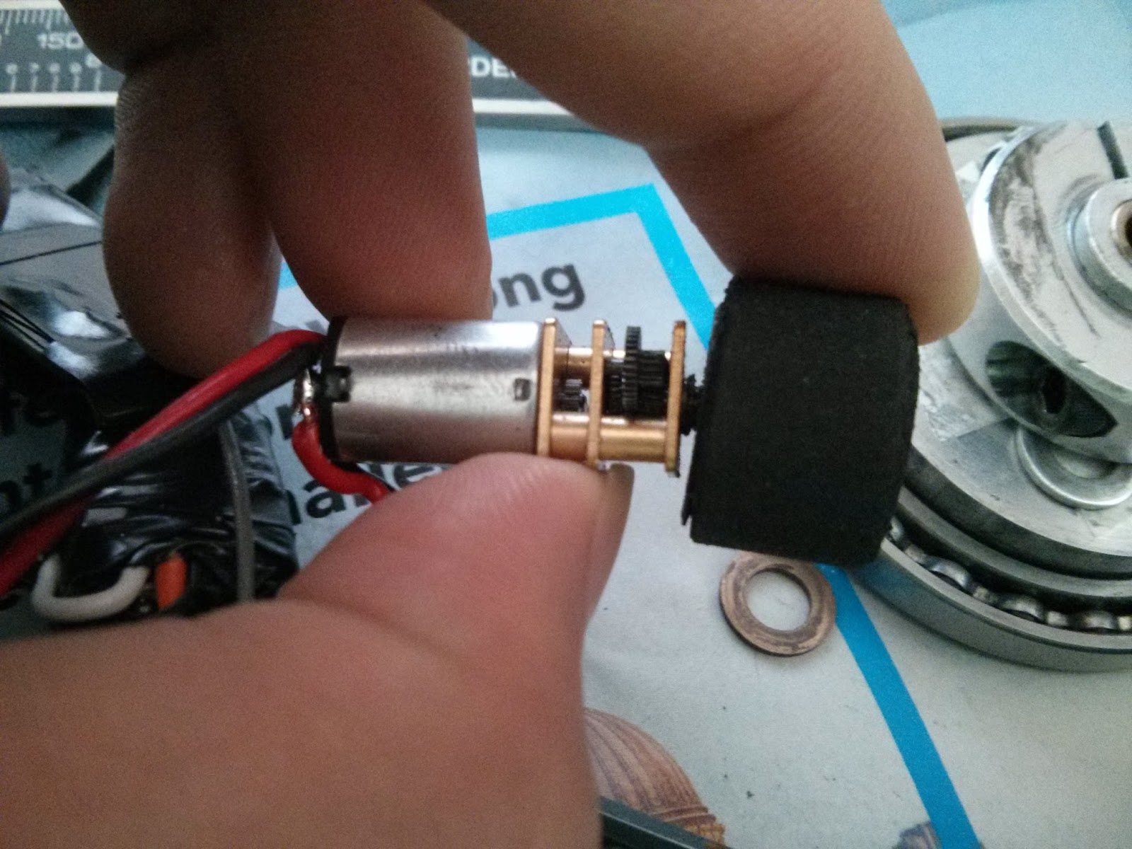
The robot used two fasteners total (set screw for each wheel). Carpet tape and fiber back strapping tape was the primary fastener. Most of the frame was scrap half-inch foamboard (stiff paper backed foam). It used a couple of gold sparks, the 33.3:1 variant.
A tail told you which direction was front.
Due to a complete lack of pushing power or other method of attacking, HAMster Ball only competed in two matches at Moto. The first one was against a Weta kitbot which didn't have much weapon range, so it did nothing.
The second match was against a robot with a proper weapon, so it showed off its self-righting ability before getting popped in half.
While I hoped it could have gone against a vertical bar robot, the fact it was able to show off the buoying action was good enough.
Stability Margins was supposed to fix all the things wrong with Final Exam. The main points were the weapon being unstable and the delicate drive system. The robot ended up stable. A little too stable. So stable it didn't move at all. I wasn't a fan of it and forgot to take many pictures.
Design
The main driving force for this design was to try to keep the flatness of the Final Exam, but also get inverted driving. The weapon motor design was good, so I reused that. For stability, I used a disk instead of a bar. But to get the bar's ability to have a small target for out-of-plane hits, the tooth on the disk sticks out a lot. To help save the drive motors, the wheels were indirectly driven with belts and the motors and gearboxes supported by aluminum clamps.
The weapon motor was largely the same, but with a bearing in the middle instead of a bushing. The blade itself was held on by six M3 screws, which was a mistake since they shear really easily. The blade was kept away from the frame with low head screws.
This was a 12 tooth, 14 pole motor, wound with 12 turns of 22 gauge wire.
The drive wheels were made of rubber vacuum tubing and HDPE hubs. Both materials sucked to work with. The tubing was abrasion resistant, not quite concentric, and impossible to cut accurately. The hubs kept slipping in the lathe chuck and bent around tooling, calling for scary oversizes.
An attempt to glue the hubs onto the tires with JB Weld. As if anything can stick on HDPE.
The belts were made by using the soldering iron to heat the belting up to the proper temperature and mushed together by hand. Many attempts and swears were had to get the belts the proper length.
Whoops
Performance
The first problem is the center of mass is way far out from the drive wheels at almost 3.5 inches.
The white and black mark is the center of mass.
It was far enough to prevent driving on even smooth surfaces. There was simply not enough weight over the wheels. As a last minute fix, I drilled holes in the side of the robot so the motors could directly drive an additional set of wheels.
This made the robot four wheel drive, but only two wheels at a time. To protect the new wheels, I hot wire cut some foam. Basically adding water wings to the bot.
Yet another case of me taking a slick robot and making it tacky.
The outboard wheels drastically improved driving ability. But, since they were exposed, after every match I had to straighten the axles. Bent axles were the least of the drivetrain problems unfortunately. Due to the extremely rigid all metal frame, impacts from the weapon were relatively undamped as they traveled through the frame, up the very rigid aluminum motor clamps, and into the motor where they destroyed the brushes. During a match the robot will noticeably degrade with each hit on the opponent. As the competition went on, I ran out of motors to swap in and ran the robot with only three wheels, two wheels touching the ground at a time. This flaw eventually cost me the championship.
Things Learned
PAY ATTENTION TO YOUR CENTER OF GRAVITY!
Lite Flite wheels are great, seeing how they managed to keep gearboxes from damage.
At Dragoncon 2013, prior to robot battles, I had some spare time and spare parts. This, plus discovering the new hot wire foam cutter the Invention Studio had just acquired, led to a joke robot, also known as an "assbot", as they are not half-assed, but complete and full of ass.
Assbots have a few rules. They must not be planned ahead of time (Agent Colson is not an assbot), made as soon before the competition as possible (the pressure inspires the creative juices) and use as few fasteners as possible, to allow for creative design.
This assbot is called HAM, a beetleweight. It is the first of its series, a whole lineage of HAM related assbots. Unfortunately pictures of HAM are few.
The top half of the robot.
HAM is made mostly of foam and googly eyes. It used a pair of cheap eBay motors running on 2S (8.4V) and Vex Motor Controllers 29s. With a very narrow wheelbase, large wheels, and fast motors, it was incredibly difficult to drive straight and turn in a controlled manner. A hunk of 1/4" titanium was strapped to the top of the robot like a mohawk. It consisted of at least 1/3 of the total weight of the robot.
The wheels were waterjet and glued directly onto the motor output shafts with Loctite. O-rings were hot-glued onto the rims for traction.
On the back of the robot HAM was extruded from more foam.
The only method of attack that HAM had was to push. Since neither are the motors torquey nor the wheels grippy, HAM wasn't that good at pushing.
However, if it could remain right-side-up, HAM could take hits, and won by not breaking itself.
Back in the combat robot game! This time, a more traditional (and proven) drivetrain, with a hefty steel bar. This is the three pound Final Exam.
Lots of inspiration from Charles' Pop Quiz, a one pound robot of very similar design.
The primary goal of this robot was to out-reach any and all other weapons out there. This was taken care of by using the overhead bar design, allowing the weapon to completely surround the robot at a radius of 13 inches. Later I realize there are other kinds of limits to this range.
The second goal was to be flat enough to fit underneath most other horizontal spinners. This was tricky. Most of the components I used before were somewhat medium sized in each dimension. For a flat robot this was unacceptable. Compromises were made. Many somewhat underpowered drive motors, for example, instead of a few sufficiently strong motors. In the end I was able to make the weapon 23 mm (0.9 in) above the ground. Lets get started with details.
Weapon Design
The Motor
To minimize height contributions from the weapon assembly the weapon motor needed to be as flat as possible, and the weapon as close to the motor as possible.
To solve motor height, I started with one of Hobbyking's "Multi-rotor motor" which trades off height for width. Instead of having a long motor with a large magnetic field, it uses a wide design to get more torque with a smaller magnetic field. This also has the side effect of making the motor slower, at 620 Kv. For comparison a motor I would otherwise use if I didn't have this size limitation would be at least 1000 Kv.
To solve motor to weapon distance, I decided on a hub motor design, mounting the weapon directly onto the motor. This works great with the wide and flat motor, since the lower speed and high torque are exactly what the hub motor needs. However, it adds some design considerations, as now the weapon has to withstand weapon impacts.
After fiddling in CAD, this design came out. The outer ring is a pretty wide 72 mm, but the height from the bottom to the blade is only 18.8 mm. The outer ring is 14 mm tall, leaving plenty of room for a top plate.
The ring of magnets was cut away from the original motor can, reinforced with JB weld, and pressed into the new motor can. The old stator was removed from its mount, rewound (dLRK, 12T per tooth, single strand 22 AWG), and pressed onto a new mount.
To somewhat protect the motor from shock, the blade was not rigidly fixed to the motor's rotation. Instead, it used a shaft collar, which is pressed against the blade before tightening it, allowing there to be some slip if it really has to.
At the center of the motor is a long bronze bushing supporting both the weapon and the shaft collar holding the weapon on. I used a bushing instead of a bearing for the small size and its length.
The can is supported on the outside with a big thin section bearing and a wide support to soak up radial loads. When assembled, the top plate overlaps the bearing, holding it and the motor can firmly in place.
However, this design has some problems, which I would soon discover.
Due to the long bushing, the motor is extremely sensitive to axial misalignment. Even after tapping the dead shaft support in the lathe to ensure co-axial-ness, I still had to loosen and retighten all the components every time I removed the dead shaft. Otherwise there would be binding and lots of heat generated. While I didn't mind loosening the 19 screws holding the weapon together too much, it became a problem when things got misaligned from a big hit from another robot.
Another problem is that shaft collars are not immovable when tightened. I found that it is most certainly possible for the blade to pry off the shaft collar even when it is tightened so far it deforms its mount. I added double sided tape to the contacting face of the motor can to help with slipping when this occurred.
In real life!
Aside from those two shortcomings, the motor did prove to be quite resilient, absorbing abuse from the weapon tumbling at full speed, hitting concrete and other robots, and a hefty out-of-plane hit from the spinning drum of a Weta clone.
The Blade
The blade was designed to be as long as I could make, with restrictions on width and weight. The width is twice the diameter of the center hole (9/16 in), recommended by the Riobotz combat robot tutorial to optimize the strength around the center hole.
At the tips they are pointy to enhance grabbing ability. Looking closely you can see the opposite corners are rounded, so they don't protrude beyond the radius set by the flat sides of the blade.
I chose S7 tool steel for this weapon, through hardened and tempered to somewhere in the mid 50's HRc. This way it will hold an edge (since it is pretty hard) yet still be able to absorb impacts without shattering. To squeeze out a bit more inertia, I used oversized 5/32" stock.
Right after tempering in the kitchen oven
Luckily the tempering temperature was within kitchen oven range, at 550 F.
Of course, this blade is not without downsides. First, it has a huge moment of inertia for this weight class due to its length. While an 1/8" thick six inch diameter steel disk has a moment around 3 lb-in^2, this bar has 11 lb-in^2, making it kinda hard to start spinning quickly.
The other issue is that bars don't precess like disks. Instead of smooth motions, bars tend to tumble when rotated out of plane. This instability can be seen with Last Rites, the horizontal spinner, in this match at around 0:19.
Now imagine what happens if the blade was bigger than the robot. Final Exam has a bad habit of tossing itself, sometimes 20 feet into the air (sorry, no videos of this as I was more worried about robots headed in my direction).
When it was able to spin up it could do massive damage, such as this unfortunate colson wheel.
Non-motor related things (Frame, drive, assembly)
This was a very waterjet-heavy design (old Invention Studio habits die hard). The main frame consists of a hamburger of 14mm thick aluminum sandwiched between two thin plates of aluminum.
The meat. Note the cutouts at the corners for the wheels and the pockets for the motor gearboxes.
Four Sanyo/Pololu micro gearmotors are mounted at the corners. Normally these are used for one-pound robots but I gave it a shot.
I attempted to run them at 4S (16.8V) but it melted the solder inside, so the drive motors were ran on 2S (8.4V).
Rubber tubing was glued onto aluminum hubs and finished on the lathe for the wheels.
The front was machined at an angle and covered with what I think was 1/32" grade 5 titanium.
Shady way of doing it.
Proper way of doing it.
The weapon motor stator was rewound to 12 turns dLRK with 22 gauge wire.
The batteries are split into a pair of 2S (8.4V) packs. The weapon motor runs on them in series (16.8V) while the drive motors run on just one pack, due to motor design limitations. This also requires two power switches to avoid putting the high voltage circuit in reverse polarity.
When the blade was heat treated and tempered, it came out curved, causing dynamic instability and the robot to end up upside-down. To unbend a heat treated steel bar, it required putting quite a large curve on it in the vise while blow-torching it.
I was pleased with the overall slimness of the robot. I managed to undercut a rather tall midcutting robot with my overhead bar.
To try to add some self-righting capability, I put a hat on the bot, completely ruining how sleek it looked. It consisted of an aluminum tube and a plastic disposable salad bowl.
Before.
After.
Faces were added to help out.
Performance
Underwhelming. It was slow to spin up and terribly unstable. The drive motors were not shock mounted or doubly supported so they bent a little.
The hat came off halfway though a match and prevented the weapon from spinning up. A significant portion of robot damage was self-inflicted.
On the plus side, the weapon bar and weapon motor performed admirably. The bar took a direct hit on the end from a drum and kept going. The weapon motor also endured the hit, despite the long cantilevering weapon. I still use the weapon bar as a crowbar and the basic weapon motor design was reused in the next two robots.
If I were to remake this robot I would definitely shorten the blade to help with instability and use much softer tires to protect the drive motors. However, the complete lack of inverted driving was unacceptable to me and I moved on to a different design.