Back in the combat robot game! This time, a more traditional (and proven) drivetrain, with a hefty steel bar. This is the three pound Final Exam.


Lots of inspiration from Charles' Pop Quiz, a one pound robot of very similar design.
The primary goal of this robot was to out-reach any and all other weapons out there. This was taken care of by using the overhead bar design, allowing the weapon to completely surround the robot at a radius of 13 inches. Later I realize there are other kinds of limits to this range.
The second goal was to be flat enough to fit underneath most other horizontal spinners. This was tricky. Most of the components I used before were somewhat medium sized in each dimension. For a flat robot this was unacceptable. Compromises were made. Many somewhat underpowered drive motors, for example, instead of a few sufficiently strong motors. In the end I was able to make the weapon 23 mm (0.9 in) above the ground. Lets get started with details.
Weapon Design
The Motor
To minimize height contributions from the weapon assembly the weapon motor needed to be as flat as possible, and the weapon as close to the motor as possible.To solve motor height, I started with one of Hobbyking's "Multi-rotor motor" which trades off height for width. Instead of having a long motor with a large magnetic field, it uses a wide design to get more torque with a smaller magnetic field. This also has the side effect of making the motor slower, at 620 Kv. For comparison a motor I would otherwise use if I didn't have this size limitation would be at least 1000 Kv.
To solve motor to weapon distance, I decided on a hub motor design, mounting the weapon directly onto the motor. This works great with the wide and flat motor, since the lower speed and high torque are exactly what the hub motor needs. However, it adds some design considerations, as now the weapon has to withstand weapon impacts.


To somewhat protect the motor from shock, the blade was not rigidly fixed to the motor's rotation. Instead, it used a shaft collar, which is pressed against the blade before tightening it, allowing there to be some slip if it really has to.
At the center of the motor is a long bronze bushing supporting both the weapon and the shaft collar holding the weapon on. I used a bushing instead of a bearing for the small size and its length.
The can is supported on the outside with a big thin section bearing and a wide support to soak up radial loads. When assembled, the top plate overlaps the bearing, holding it and the motor can firmly in place.
However, this design has some problems, which I would soon discover.
Due to the long bushing, the motor is extremely sensitive to axial misalignment. Even after tapping the dead shaft support in the lathe to ensure co-axial-ness, I still had to loosen and retighten all the components every time I removed the dead shaft. Otherwise there would be binding and lots of heat generated. While I didn't mind loosening the 19 screws holding the weapon together too much, it became a problem when things got misaligned from a big hit from another robot.
Another problem is that shaft collars are not immovable when tightened. I found that it is most certainly possible for the blade to pry off the shaft collar even when it is tightened so far it deforms its mount. I added double sided tape to the contacting face of the motor can to help with slipping when this occurred.
 |
| In real life! |
Aside from those two shortcomings, the motor did prove to be quite resilient, absorbing abuse from the weapon tumbling at full speed, hitting concrete and other robots, and a hefty out-of-plane hit from the spinning drum of a Weta clone.

The Blade

The blade was designed to be as long as I could make, with restrictions on width and weight. The width is twice the diameter of the center hole (9/16 in), recommended by the Riobotz combat robot tutorial to optimize the strength around the center hole.
At the tips they are pointy to enhance grabbing ability. Looking closely you can see the opposite corners are rounded, so they don't protrude beyond the radius set by the flat sides of the blade.

 |
| Right after tempering in the kitchen oven |
Of course, this blade is not without downsides. First, it has a huge moment of inertia for this weight class due to its length. While an 1/8" thick six inch diameter steel disk has a moment around 3 lb-in^2, this bar has 11 lb-in^2, making it kinda hard to start spinning quickly.
The other issue is that bars don't precess like disks. Instead of smooth motions, bars tend to tumble when rotated out of plane. This instability can be seen with Last Rites, the horizontal spinner, in this match at around 0:19.
Now imagine what happens if the blade was bigger than the robot. Final Exam has a bad habit of tossing itself, sometimes 20 feet into the air (sorry, no videos of this as I was more worried about robots headed in my direction).
When it was able to spin up it could do massive damage, such as this unfortunate colson wheel.

Non-motor related things (Frame, drive, assembly)
This was a very waterjet-heavy design (old Invention Studio habits die hard). The main frame consists of a hamburger of 14mm thick aluminum sandwiched between two thin plates of aluminum. |
| The meat. Note the cutouts at the corners for the wheels and the pockets for the motor gearboxes. |
Four Sanyo/Pololu micro gearmotors are mounted at the corners. Normally these are used for one-pound robots but I gave it a shot.

I attempted to run them at 4S (16.8V) but it melted the solder inside, so the drive motors were ran on 2S (8.4V).

Rubber tubing was glued onto aluminum hubs and finished on the lathe for the wheels.

The front was machined at an angle and covered with what I think was 1/32" grade 5 titanium.
 |
| Shady way of doing it. |
 |
| Proper way of doing it. |
The weapon motor stator was rewound to 12 turns dLRK with 22 gauge wire.

The batteries are split into a pair of 2S (8.4V) packs. The weapon motor runs on them in series (16.8V) while the drive motors run on just one pack, due to motor design limitations. This also requires two power switches to avoid putting the high voltage circuit in reverse polarity.

When the blade was heat treated and tempered, it came out curved, causing dynamic instability and the robot to end up upside-down. To unbend a heat treated steel bar, it required putting quite a large curve on it in the vise while blow-torching it.

I was pleased with the overall slimness of the robot. I managed to undercut a rather tall midcutting robot with my overhead bar.

To try to add some self-righting capability, I put a hat on the bot, completely ruining how sleek it looked. It consisted of an aluminum tube and a plastic disposable salad bowl.
 |
| Before. |
 |
| After. |
Faces were added to help out.


Performance
Underwhelming. It was slow to spin up and terribly unstable. The drive motors were not shock mounted or doubly supported so they bent a little.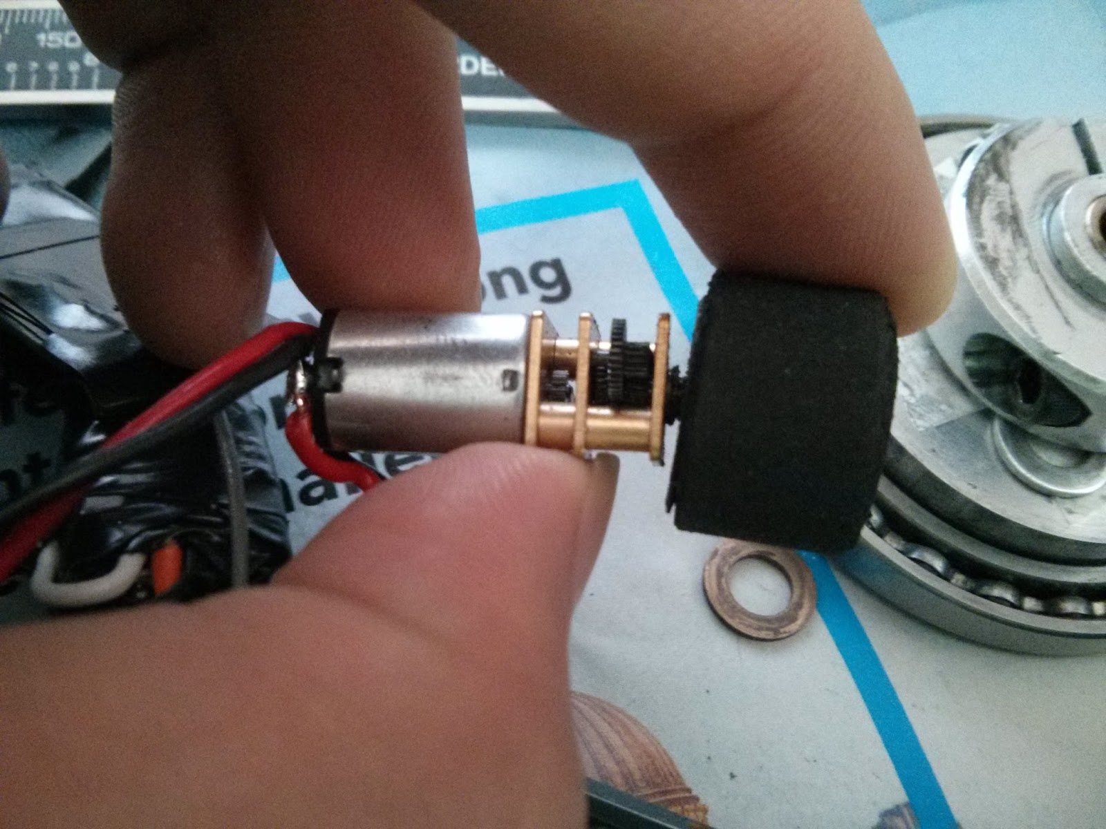
The hat came off halfway though a match and prevented the weapon from spinning up. A significant portion of robot damage was self-inflicted.

On the plus side, the weapon bar and weapon motor performed admirably. The bar took a direct hit on the end from a drum and kept going. The weapon motor also endured the hit, despite the long cantilevering weapon. I still use the weapon bar as a crowbar and the basic weapon motor design was reused in the next two robots.
If I were to remake this robot I would definitely shorten the blade to help with instability and use much softer tires to protect the drive motors. However, the complete lack of inverted driving was unacceptable to me and I moved on to a different design.